Welcome!
Please, enjoy our completely free circuit diagrams and electronics projects database!


Random circuits
Here are some of over 800 projects from our free circuit diagrams database. For more, try browsing categories menu on the left.
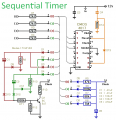 This timer will provide a sequence of up to ten separate events. The length of each event is set independently. And the sequence will run a fixed number of times - or repeat continuosly. The individual events within the sequence - can be made to repeat and/or overlap. The accompanying Support Material includes a detailed description of how the Cmos 4017 works....
[read more]
This timer will provide a sequence of up to ten separate events. The length of each event is set independently. And the sequence will run a fixed number of times - or repeat continuosly. The individual events within the sequence - can be made to repeat and/or overlap. The accompanying Support Material includes a detailed description of how the Cmos 4017 works....
[read more]
 Here is the simplest melody generator circuit you can make using an IC.The UM66 series are CMOS IC’s designed for using in calling bell, phone and toys. It has a built in ROM programmed for playing music. The device has very low power consumption.Thanks for the CMOS technology.The melody will be available at pin3 of UM66 and here it is amplified by using Q1 to drive the speaker.Resistor R1 limits the base current of Q1 within the safe values.Capacitor C1 is meant for noise suppression....
[read more]
Here is the simplest melody generator circuit you can make using an IC.The UM66 series are CMOS IC’s designed for using in calling bell, phone and toys. It has a built in ROM programmed for playing music. The device has very low power consumption.Thanks for the CMOS technology.The melody will be available at pin3 of UM66 and here it is amplified by using Q1 to drive the speaker.Resistor R1 limits the base current of Q1 within the safe values.Capacitor C1 is meant for noise suppression....
[read more]
 These are two - easy to build - relay-based alarms. You can use them to protect your motorcycle - but they have many more applications. If you use relays with 6-volt coils - they'll protect your "Classic Bike". Both alarms are very small. The completed boards occupy about half a cubic-inch - 8 cc. The standby current is zero - so they won't drain your battery....
[read more]
These are two - easy to build - relay-based alarms. You can use them to protect your motorcycle - but they have many more applications. If you use relays with 6-volt coils - they'll protect your "Classic Bike". Both alarms are very small. The completed boards occupy about half a cubic-inch - 8 cc. The standby current is zero - so they won't drain your battery....
[read more]
 This simple circuit tests speakers, microphones, transformers and voltage. It's basically a very low frequency oscillator that produces extremely short 'fruity' pulses. The type of sound produced is very easy to hear and to determine the precise direction it is coming from, thus making it ideal for checking the phasing in multiple speaker installations. It is also very useful for car stereo installations as well as public address systems where it can drive dozens of speakers directly on a 100V or 70V line system....
[read more]
This simple circuit tests speakers, microphones, transformers and voltage. It's basically a very low frequency oscillator that produces extremely short 'fruity' pulses. The type of sound produced is very easy to hear and to determine the precise direction it is coming from, thus making it ideal for checking the phasing in multiple speaker installations. It is also very useful for car stereo installations as well as public address systems where it can drive dozens of speakers directly on a 100V or 70V line system....
[read more]
 This circuit features an intermittent siren output and automatic reset. It can be operated manually using a key-switch or a hidden switch; but it can also be wired to set itself automatically when you turn-off the ignition. By adding external relays you can immobilize the bike, flash the lights etc....
[read more]
This circuit features an intermittent siren output and automatic reset. It can be operated manually using a key-switch or a hidden switch; but it can also be wired to set itself automatically when you turn-off the ignition. By adding external relays you can immobilize the bike, flash the lights etc....
[read more]
 This circuit automatically turns a motor cycle's headlight on and off, independently of both the light and ignition switches, provided the battery is fully charged. The first stage uses the 22O resistor and ZD1 to hold transistor Q1 off while the motor is not running; it draws about 2mA. Once the battery voltage exceeds 7.0V during charging, Q1 begins to turn on....
[read more]
This circuit automatically turns a motor cycle's headlight on and off, independently of both the light and ignition switches, provided the battery is fully charged. The first stage uses the 22O resistor and ZD1 to hold transistor Q1 off while the motor is not running; it draws about 2mA. Once the battery voltage exceeds 7.0V during charging, Q1 begins to turn on....
[read more]