- Hearing Aid
- Amplified Ear
- A Low Cost Hearing Aid
- Studio Series Stereo Headphone Amplifier
- Stereo Headphone Amplifier Circuit Schematic
- Pure Class-A Headphone Amplifier Schematic
- Portable Headphone Amplifier Circuit
- A Hiqh Quality Headphone Amplifier Schematic
- Ultra-High Fidelity High Power Amplifier Reference Design
- Speach Amplifier
- DC-Coupled Audio Amplifier
- A Low Power Wireless Audio Power Amplifier
- 8 Watt Audio Power Amplifier Schematic
- 7 Watt Audio Power Amplifier Circuit Schematic
- 60 Watt Audio Power Amplifier Circuit Diagram
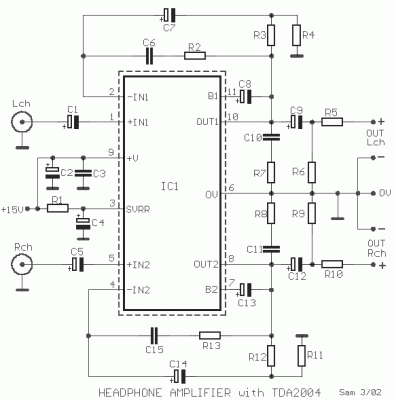
Headphone amplifier with TDA2004
Description
A opamp. medium power, here its used as amplifier of headphones with possibility drive low loads. It contains in a nutshell two amplifiers. The voltage gain, has been determined in 40dB, from the R3-4 and R11-12, for each channel, respectively. The restriction of bandwidth for each unit is regulated by the combination of R12, C2 and R13, C15, in 22KHZ. The R5, R10 attend to the adaptation of impedance earphones. The resistors R6 and R9 discharge the capacitors C9 and C12, in order that when we connect the headphones in the plug, not we have annoying noise. The circuit has very good characteristics as low distortion, noise and satisfactory frequency response. The requirement of circuit in current is 150mA, roughly, with voltage supply + 15V. The IC1 should be placed on a suitable heatsink.
Circuit diagram
Part List
- R1=120Kohm
- R2-13=330 ohm
- R3-12=2.2Kohm
- R4-11=27 ohm
- R5-10=22 ohm
- R6-9=1.2Kohm
- R7-8=1.2 ohm
- C1-4-5=10uF 16V
- C2=100uF 25V
- C3-10-11=100nF 100V MKT
- C6-15=3.3nF 100V MKT
- C7-8-13-14=100uF 16V
- C9-12=470uF 25V
- IC1=TDA2004 in Heatsink
