similar circuits
- Pump it up: Mp3 Booster
- Bass Booster Circuit
- Audio Booster
- Symmetrical Class A Preamplifier
- Symmetrical Preamplifier Class A
- Modular Class A Buffer preamplifier
- Moduler Preamplifier Circuit Diagram
- Portable Microphone Preamplifier Circuit Schematic
- Stereo Preamplifier With Bass Boost
- Phono Preamplifier
- Modular Preamplifier Switching Center
- Portable Microphone Preamplifier
- Phono Preamplifier
- Electronic Stethoscope
- Speaker Microphone Circuit
Symmetrical Preamplifier Class A
Description
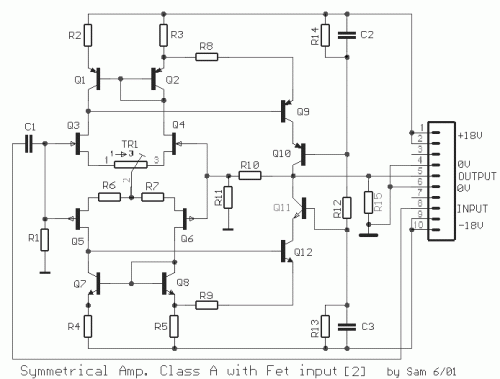
This is a symmetrical amplification unit circuit, more composed, modified by a construction which was proposed some years ago by Lisley Hood. The most important reason is to get the right transistor FET at differential amplifier at input. In spite of all this it is a circuit which provides, current mirror stage of both sides, with the result of lessening the overall negative feedback. The exactness of the matches of the transistors - resistances are determined and for the details. The trimmer TR1, make less the offset voltage at input.
Circuit diagram
Part List
- R1= 47Kohms
- R2-4= 220 ohms
- R3-5= 100 ohms
- R6-7= 470 ohms
- R8-9= 220 ohms
- R10= 5.6 Kohms
- R11= 1 Kohms
- R12= 10 Kohms
- R13-14= 820 ohms
- R15= 47 ohms
- TR1= 1 ohms trimmer
- C1= 4.7uF 100V MKT
- C2-3= 100nF 63V MKT
- Q1-2= BC214
- Q9= BC214
- Q10= BC212
- Q11= BC182
- Q7-8= BC184
- Q12= BC184
- Q3-4= 2N5457
- Q5-6= 2N5460
