- Paraphase Tone Controller
- Digital Volume Control
- Automatic Loudness Control Circuit Schematic
- 10 Band Graphic Equalizer
- 6-Band Graphic Equalizer
- 5 Band Graphic Equalizer
- 3 Band Equalizer
- Equalizer with Parametric Mid
- Audio Auto Fade
- Stereo Preamplifier with adjustment tone
- Automatic Loudness Control
- Simple Digital Volume Control
- Bass-treble tone control circuit
Audio Auto Fade
Description
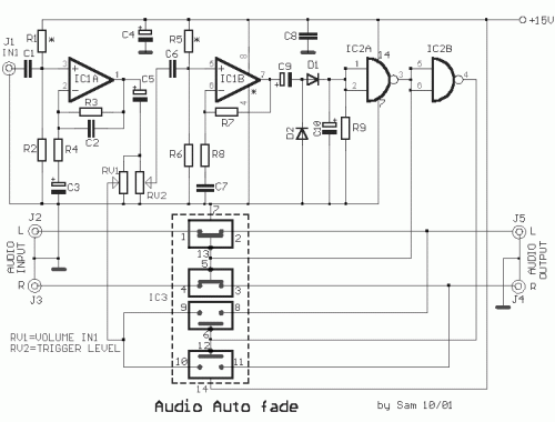
This circuit is design, in order to is heard the voice above the music. Useful for DJ, for small radio stations, for statements above the music, in shops etc. Also we can him use in applications that we want to handle some unit with our voice. As it has the circuit has become forecast for stereo music and monophonic microphone, but can be modified and be adapted in the needs or in the use that we want, him we use. The forecast in the sector of power supply is single + 15V, but can use symmetrical ± 9V, from two batteries until ± 15V. In a such case it will be supposed are removed the resistances R1-R5 and pin the 4 IC1, it is link to the negative voltage, the other pins completed remain, in this case, as have. The circuit round the IC1A, is a amplifier that strengthens a microphone signal, can be modified so as to we change the rate of gain of unit, so as to him we adapt in our needs. By there the acoustic signal branch. A part via the pontesomemeter RV1, that regulates the intensity of sound, is applied in the two switches of IC3, in the pins 9 and 10, and it remains pending, one and the switches do not have excitation in 6-12. This switches when they do not have excitation, they present resistance, at length of contacts 8-9 and 10-11, 10MΩ roughly. On the contrary if exists excitation then this resistance falls in 300Ω roughly, allowing in the signal to pass from means. The himself is also in effect for remainder switches that constitute the IC3. Via the RV2 and the IC2Β, that is a amplifier, that strengthens still more the signal, so that it reaches in level such, it is rectified from the D1-2, C10 and R9. The circuit provides a DC interrupted signal, in the rythm of signal IN1, signal which is used in order to changes the situation of IC2A and IC2BIn situation of calm the exits of (IC2A - IC2B), the 3 it has high rate and the 4 it has low rate. Thus switches IC3Α and IC3B, are found in situation ON (closed) allowing the stereo signal it passes from means. When it exists sound excitation in entry J1 then according to the above description we have change of situations of IS2A-B, so that changes also the situation of switches of IC3, so switches A-B, open (OFF) and the C-D to close (ON), reversing the previous situation. Thus is interrupted the stereo signal and is allowed the flow of signal, from entry J1.In order to we try the circuit, we regularly put a musical program in entries J2-3, the program it should it passes in exits J4-5, without no reduction or distortion and for the two channels. We connect a microphone in entry J1, we regulate the RV2 (trigger), in his extreme place to capacitor C5 and we slowly begin him to turn on the contrary until it reaches some point, to pass the signal of microphone. Likely when finishes the speech, the circuit vibrate. If happens such something, likely RV2 it has big resistance. With little experimentation in the gain of IC1A-B, and in the regulation of RV2, we can achieve, the yield that we want. If we use other source of signal in entry J1, it will be supposed we make new regulation.
Circuit diagram
Part list
- R1-2= 1Mohms
- R5-6= 1Mohms
- R5-6= 1Mohms
- R3= 150Kohms
- R4-8= 1Kohms
- R7= 220Kohms
- R9= 470Kohms
- C1-6= 220nF 100V MKT
- C2= 100pF ceramic
- C3= 1uF 25V
- C4= 47uF 25V
- C5= 10uF 25V
- C7-8= 100nF 100V MKT
- C9-10= 4.7uF 25V
- D1-2= 1N4148
- IC1= TL072
- IC2= 4011
- IC3= 4016 - 4066
- J1-2= RCA Famale Plung
- RV1= 47Kohms Log. pot.
- RV2= 47Kohms Lin. pot.
- All Resistors is 1/4W 1-5%
