- Dancing LEDs Circuit Diagram
- Dark Activated Led or Lamp Flasher
- Two Flashing LEDs Circuit Schematic
- Dicing With LED's
- Bicycle Back Safety Light Circuit Schematic
- AC 220 Volts Flashing Lamps Circuit
- Smooth Flasher Circuit Diagram
- Portable Lamp Flasher
- One Of Nine Sequencer
- Led or Lamp Flasher Circuit
- LED or Lamp Pulsar Circuit
- High-intensity LED Warning Flasher
- Flashing Eyes
- Fading Leds Circuit Diagram
- 12 Stage Neon Sequencer (NE-2 / NE-51)
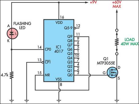
One Of Nine Sequencer
Description
This novel circuit uses a flashing LED as the clock input for a 4017 decade counter. Typical flashing LEDs (eg, DSE cat Z-4044) flash at about 2Hz so the outputs Q0-Q9 will cycle through at that rate. For example, Q0 will turn on for half a second, then Q1, then Q2 etc up to Q8 then it will start at Q0 again. Up to nine outputs can be used. If you want fewer outputs, connect an earlier output to MR, pin 15. If MR is not used, connect it to 0V.
Circuit diagram:
Uses for the circuit include sequencing different strings of Christmas lights etc. The resistor from CP0 to ground can be anywhere from about 330O to about 10kO. Lower values will cause the LED to flash more brightly if that is required. With a 4.7kO resistor as shown, the clock input CP0 (pin 14) will alternate between about 2V and 7V. To drive loads of up to 40W at up to 60V, connect each output to the gate of a 2N3055E or equivalent Mosfet (MTP3055E etc), as shown for Q0.
circuit from http://www.extremecircuits.net/2010/05/one-of-nine-sequencer.html
