Battery charger schematics
 This simple circuit can give regulated 4.7 volts for charging a mobile phone. USB outlet can give 5 volts DC at 100mA current which is sufficient for the slow charging of mobile phones. Most of the Mobile Phone batteries are rated 3.6 volts at 1000 to 1300 mAh. These battery packs have 3 NiMh or Lithium cells having 1.2 volt rating. Usually the battery pack requires 4.5 volts at 300-500 mA current for fast charging....
[read more]
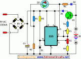 This automatic NiCd charger for 9V NiCd batteries is using 555 timer properties and is very easy to build. Why is an automatic 9 volts NiCd battery charger? Because you can leave the battery for charging as much as you like: it will be always completely charged and ready for use when is needed. It wont be overcharged and it will not discharge. With the values presented in the circuit diagram, the battery charger NiCd circuit is suitable for 6V and 9V batteries....
[read more]
 This NiCd battery Charger can charge up to 7 NiCd batteries connected in series. This number can be increased if the power supply is increased with 1.65V for each supplementary battery. If Q2 is mounted on a proper heatsink, the input voltage can be increased at a maximum of 25V. Unlike most of comercial NiCd chargers available on the market, this charger has a reverse polarity protection. Another great quality is that it does not discharge the battery if the charger is disconnected from the power supply....
[read more]
 Using the USB port on your computer to charge your player’s batteries is not always practical. What if you do not have a computer available at the time or if you do not want to power up a computer just for charging? Or what if you are traveling? Chargers for Mobile Phones iPods and MP3 players are available but they are expensive and you need separate models for charging at home and in the car....
[read more]
 Here is an ideal Mobile charger using 1.5 volt pen cells to charge mobile phone while traveling. It can replenish cell phone battery three or four times in places where AC power is not available. Most of the Mobile phone batteries are rated at 3.6 V/500 mA. A single pen torch cell can provide 1.5 volts and 1.5 Amps current. So if four pen cells are connected serially, it will form a battery pack with 6 volt and 1.5 Amps current. When power is applied to the circuit through S1, transistor Q1 conducts and Green LED lights....
[read more]
 Mobile phone chargers available in the market are quite expensive. The circuit presented here comes as a low-cost alternative to charge mobile telephones/battery packs with a rating of 7.2 volts....
[read more]
 Charging of the mobile phone, cellphone battery is a big problem while traveling as power supply source is not generally accessible. If you keep your cellphone switched on continuously, its battery will go flat within five to six hours, making the cellphone useless....
[read more]
 This circuit is Ideal for car use. It has ability to transform a mains adapter in to a charger . This one can be used to charge cellular phone, toys, portables, video batteries, MP3 players, ... and has selectable charge current. An LED is located in circuit to indicate charging. Can be built on a general purpose PCB or a veroboard....
[read more]
 This circuit was developed to charge the Lithium-Polymer cells used in a model aircraft. Lithium-Polymer cells are incredibly lightweight compared to Ni-cad battery packs of the same voltage and amp-hour rating. Their only drawback is that they require a rigid charge and discharge regime to achieve maximum life....
[read more]
 The SLA battery is charged from the vehicle’s battery. When the engine is running, the voltage remains fairly constant, which greatly simplifies the charging circuit. If the SLA battery is fully charged, any further charging current from the vehicle battery is limited by a 3.3W 5W resistor (R1). If the SLA battery is deeply discharged, the voltage drop across this resistor will be enough to bias on PNP transistor Q1. This will turn on P-channel Mosfet Q2 and it will provide further charging current via R2, effectively becoming a 2-step charger....
[read more]
 Most off-the-shelf car battery chargers cannot not be left connected to the battery for long periods of time as over-charging and consequent battery damage will occur. This add-on circuit is placed in series with the battery being charged and is powered by the battery itself. In effect, the circuit uses a high-current Mosfet to control the charging current and it turns off when the battery voltage reaches a preset threshold. Power for the circuit is fed from the battery to 3-terminal regulator REG1 which provides 8V....
[read more]
 Most mobile chargers do not have current/voltage regulation or short-circuit protection. These chargers provide raw 6-12V DC for charging the battery pack. Most of the mobile phone battery packs have a rating of 3.6V, 650mAh. For increasing the life of the battery, slow charging at low current is advisable. Six to ten hours of charging at 150-200mA current is a suitable option. This will prevent heating up of the battery and extend its life....
[read more]
 Unlike many units, this battery charger continuously charges at maximum current, tapering off only near full battery voltage. In this unit, the full load current of the supply transformer/rectifier section was 4.4A. It tapers off to 4A at 13.5V, 3A at 14.0V, 2A at 14.5V and 0A at 15.0V....
[read more]
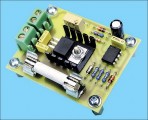 Protect your expensive batteries from discharge damage with this mini-sized electronic cutout switch. It uses virtually no power and can be built to suit a wide range of battery voltages....
[read more]
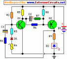 A Battery-status Indicator circuit can be useful, mainly to monitor portable Test-gear instruments and similar devices. LED D1 flashes to attire the user's attention, signaling that the circuit is running, so it will not be left on by mistake. The circuit generates about two LED flashes per second, but the mean current drawing will be about 200µA. Transistors Q1 and Q2 are wired as an uncommon complementary astable multivibrator: both are off 99% of the time, saturating only when the LED illuminates, thus contributing to keep very low current consumption....
[read more]
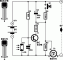 This is a small electronic switch that connects a battery to the equipment for a certain amount of time when a push-button is momentarily pressed. And we have also taken the ambient light level into account; when it is dark you won’t be able to read the display so it is only logical to turn the switch off, even if the time delay hasn’t passed yet. The circuit is quite straightforward. For the actual switch we’re using a well-known MOSFET, the BS170....
[read more]
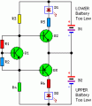 Almost all 24V power systems in trucks, 4WDs, RVs, boats, etc, employ two series-connected 12V lead-acid batteries. The charging system can only maintain the sum of the individual battery voltages. If one battery is failing, this circuit will light a LED. Hence impending battery problems can be forecast. The circuit works by detecting a voltage difference between the two series connected 12V batteries. Idle current is low enough to allow the unit to be permanently left across the batteries....
[read more]
 Don't get caught with a flat battery; this easy-to-build circuit can cut off the power to a 12V fridge or car stereo system if the battery voltages drops below critical level. Electric fridges in vans and 4WDs are a great idea but if you are not careful, they can severely discharge the battery and leave you stranded. Maybe the battery will end up with severe damage as well. The same problem applies if you have a big stereo system and you like to play it without the motor running....
[read more]
 This circuit can be useful to detect if the load of any battery charger or plug-in adapter supply is not properly connected. The load can be a set of batteries to be charged or any other type of battery or low dc voltage operated device. The circuit can safely operate over a 3 to 15V range and 1A max. Current, provided the supply voltage is about one volt higher than the voltage required by the load....
[read more]
 A simple method of charging a battery from a higher voltage battery is shown in the circuit below to the left. Only one resistor is needed to set the desired charging current and is calculated by dividing the difference in battery voltages by the charge current....
[read more]
 This circuit was build to charge a couple series Lithium cells (3.6 volts each, 1 Amp Hour capacity) installed in a portable transistor radio....
[read more]
 This is a similar circuit to the above and provides a 4 LED bar graph indicating the voltage of a common 3.6 volt Lithium - Ion recharable cell phone battery. The reference voltage is provided by a TL431 programmable voltage source which is set to 3.9 volts where the TL431 connects to the 1K resistor. The lower reference for the LED at pin 14 is set with the 5K adjustable resistor....
[read more]
 This circuit can charge automatically, fast and rightly, batteries 6V and 12V. A basic factor in the success in the circuit operation is the use of transformer [T1] of good quality with very good insulation and resistance in the short circuits....
[read more]
 Ni -Cd Batteries Charger...
[read more]
 his simple charger uses a single transistor as a constant current source. The voltage across the pair of 1N4148 diodes biases the base of the BD140 medium power transistor....
[read more]
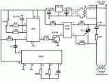 If you own a motorcycle, a motor home, a caravan, a lawn mover, a day cruiser or maybe a vintage car you must at some point had to write off a lead acid battery. When a battery is improperly charged or allowed to self-discharge as occurs during non-use, sulphate crystals build up on the battery's plates....
[read more]