- USB Powered Mobile Phone Battery Charger
- NiMh and NiCd Battery Charger Circuit
- NiCd Battery Charger With Reverse Polarity Protection
- Mobile Phone and iPod Battery Charger Circuit
- Mobile Phone Travel Charger Circuit Diagram
- Mobile Phone Battery Charger Circuit
- Mobile Cellphone Battery Charger Circuit
- Low Cost Universal Battery Charger Schematic
- Lithium-Polymer Peak Charger
- In-Car Charger And Switcher Circuit For SLA Battery
- Battery Charger Regulator
- A Friendly Charger Schematic for Mobile Phones
- 12 Volt Car Battery Charger Circuit Schematic
- Versatile Micropower Battery Protector
- Flashing-LED Battery-Status Indicator Circuit
Battery Saver Circuit Diagram
Description
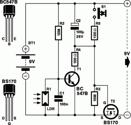
This is a small electronic switch that connects a battery to the equipment for a certain amount of time when a push-button is momentarily pressed. And we have also taken the ambient light level into account; when it is dark you won’t be able to read the display so it is only logical to turn the switch off, even if the time delay hasn’t passed yet. The circuit is quite straightforward. For the actual switch we’re using a well-known MOSFET, the BS170.
A MOSFET (T2 in the circuit) used in this configuration doesn’t need a current to make it conduct (just a voltage), which makes the circuit very efficient. When the battery is connected to the battery saver circuit for the first time, capacitor C2 provides the gate of the MOSFET with a positive voltage, which causes T2 to conduct and hence connect the load (on the 9 V output) to the battery (BT1). C2 is slowly charged up via R3 (i.e. the voltage across C2 increases).
Circuit diagram:
This causes the voltage at the gate to drop and eventually it becomes so low that T2 can no longer conduct, removing the supply voltage to the load. In this state the battery saver circuit draws a very small current of about 1 µA. If you now press S1, C2 will discharge and the circuit returns to its initial state, with a new turn-off delay. Resistor R5 is used to limit the discharge current through the switch to an acceptable level. You only need to hold down the switch for a few hundredths of a second to fully discharge C2.
In our prototype, connected between a 9 V battery and a load that drew about 5 mA, the output voltage started to drop after about 26 minutes. After 30 minutes the voltage had dropped to 2.4 V. You should use a good quality capacitor for C2 (one that has a very low leakage current), otherwise you could have to wait a very long time before the switch turns off! The ambient light level is detected using an LDR (R1). An LDR is a type of light sensor that reduces in resistance when the light level increases. We recommend that you use an FW150, obtainable from e.g. Conrad as part number 183547-89.
When there is too little light its resistance increases and potential divider R1/R2 causes transistor T1 to conduct. T1 then charges up C2 very quickly through R4, which limits the current to a safe level. This stops T2 from conducting and the load is turned off. The choice of value for R2 determines how dark it has to be before T1 starts to conduct. The battery saver circuit can be added to devices that use 6 or 9 volt batteries and which don’t draw more than 100 mA. The circuit can be built on a piece of experimenter’s board and should be made as compact as possible so that it can be built into the battery powered device.
