DC power supply schematics
 Here is an efficient 4-stage stabilised power supply unit for testing electronic circuits. It provides well regulated and stabilised output, which is essential for most electronic circuits to give proper results. The circuit provides an audio-visual indication if there is a short circuit in the PCB under test, so the power supply to the circuit ‘under test’ can be cut-off immediately to save the valuable components from damage....
[read more]
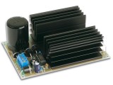 This power supply is meant as an auxiliary or as a permanent power supply for all common circuits based on a stabilized DC voltage between 3 and 30V provided that the consumption does not exceed 3A. Of course this power supply unit can also be used for other purposes. Be replacing the trimmer by a potentiometer, it may even be used as an adjustable power supply unit. A good quality heatsink must be used....
[read more]
 There is little to be said about this circuit. All the work is done by the regulator. The 7809 can deliver up to 2 amps continuous output whilst maintaining a low noise and very well regulated supply. The circuit will work without the extra components, but for reverse polarity protection a 1N5400 diode (D1) is provided at the input, extra smoothing being provided by C1. The output stage includes C2 for extra filtering, if powering a logic circuit than a 100nF (C3) capacitor is also desirable to remove any high frequency switching noise....
[read more]
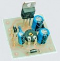 Want a regulated voltage that can be adjusted to suit your application? This Adjustable Power Supply is small, easy to build and can be adapted to produce a fully regulated voltage ranging from 1.3V to 22V at currents up to 1A....
[read more]
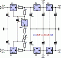 This current-limiting circuit, shown in this example as part of a small bench power supply, could in principle be used in conjunction with any dual-rail current source. The part of the circuit to the left of the diagram limits the current at the input to the dual voltage regulator (IC4 to IC7) so that it is safely protected against overload. The circuit shown produces outputs at ±15 V and ±5V. The voltage regulators at the outputs (7815/7805 and 7915/7905) need no further comment; but the current-limiting circuit itself, built around an LM317 and an LM337, is not quite so self-explanatory....
[read more]
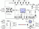 This power supply was designed for use with the ‘Simple hybrid amp’ published elsewhere in this issue. It is of course suitable for use in other applications as well. We’ve used a cascade generator for the 170 V, a switch mode supply for the 16 V, a series regulator for the 12 V and a separate transformer for the 6.3 V filament supply. We’ve chosen an LT1074CT (IC1) for the regulator, which means that the circuit can be built with relatively standard components and will have a high efficiency. The power loss is less with this device compared to a linear voltage regulator....
[read more]
 This circuit of power supply, is very simple and easy to built, it can be assembled on a general-purpose PCB, finding its materials is very easy and cost-small. The output voltage is stabilized and is regulated in the region from 0V until + 15V dc, with biggest provided current 1 A. The regulation becomes with the P1. The Q1 is classic power transistor and it needs to be placed on a cool rib (Heatsink), when it works continuously in the region of biggest current it gets hot. The type of transformer is standard in the market....
[read more]
 An increasing number of appliances draw a very small current from the power supply. If you need to design a mains powered device, you could generally choose between a linear and a switch-mode power supply. However, what if the appliance’s total power consumption is very small? Transformer-based power supplies are bulky, while the switchers are generally made to provide greater current output, with a significant increase in complexity, problems involving PCB layout and, inherently, reduced reliability....
[read more]
 This circuit is not an absolute novelty, but it is simple, reliable, "rugged" and short-proof, featuring variable voltage up to 24V and variable current limiting up to 2A. You can adapt it to your own requirements as explained in the notes below....
[read more]
 There are many circuits for low voltage regulators. For higher voltages, such as supplies for valve circuits, the situation is different. That’s why we decided to design this simple regulator that can cope with these voltages. This circuit is obviously well suited for use in combination with the quad power supply for the hybrid amp, published elsewhere in this issue. The actual regulator consists of just three transistors. A fourth has been added for the current limiting function....
[read more]
 Volt regulators such as the LM708, and LM317 series (and others) sometimes need to provide a little bit more current then they actually can handle. If that is the case, this little circuit can help out. A power transistor such as the 2N3772 or similar can be used....
[read more]
 While smoke alarms are quite cheap devices, the cost of 9V batteries quickly exceeds their purchase price. Added to that is the irritation of random beeps from the alarm as the battery reaches the end of its useful life. This circuit allows typical smoke alarms to be powered from the 12V supply in a burglar alarm while still keeping the standard 9V batteries in place. It extends the 9V battery life to that of its "shelf life" as the battery is only required to drive the smoke alarm in the event the 12V supply is removed or shorted out....
[read more]
 The high current regulator below uses an additional winding or a separate transformer to supply power for the LM317 regulator so that the pass transistors can operate closer to saturation and improve efficiency. For good efficiency the voltage at the collectors of the two parallel 2N3055 pass transistors should be close to the output voltage. The LM317 requires a couple extra volts on the input side, plus the emitter/base drop of the 3055s, plus whatever is lost across the (0.1 ohm) equalizing resistors (1volt at 10 amps), so a separate transformer and rectifier/filter circuit is used that is a few volts higher than the output voltage....
[read more]
 In this small switching power supply, a Schmitt trigger oscillator is used to drive a switching transistor that supplies current to a small inductor. Energy is stored in the inductor while the transistor is on, and released into the load circuit when the transistor switches off. The output voltage is dependent on the load resistance and is limited by a zener diode that stops the oscillator when the voltage reaches about 14 volts. Higher or lower voltages can be obtained by adjusting the voltage divider that feeds the zener diode. The efficiency is about 80% using a high Q inductor....
[read more]
 Another method of using opamps to regulate a power supply is shown. The power transformer requires an additional winding to supply the op-amps with a bipolar voltage (+/- 8 volts), and the negative voltage is also used to generate a reference voltage below ground so that the output voltage can be adjusted all the way down to 0. Current limiting is accomplished by sensing the voltage drop across a small resistor placed in series with the negative supply line....
[read more]
 This regulated power supply can be adjusted from 3 to 25 volts and is current limited to 2 amps as shown, but may be increased to 3 amps or more by selecting a smaller current sense resistor (0.3 ohm). The 2N3055 and 2N3053 transistors should be mounted on suitable heat sinks and the current sense resistor should be rated at 3 watts or more. Voltage regulation is controlled by 1/2 of a 1558 or 1458 op-amp....
[read more]
 The LM317T output current can be increased by using an additional power transistor to share a portion of the total current. The amount of current sharing is established with a resistor placed in series with the 317 input and a resistor placed in series with the emitter of the pass transistor....
[read more]
 The LM317T is a adjustable 3 terminal positive voltage regulator capable of supplying in excess of 1.5 amps over an output range of 1.25 to 37 volts. The device also has built in current limiting and thermal shutdown which makes it essentially blow-out proof....
[read more]
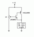 A simple but less efficient methode of controlling a DC voltage is to use a voltage divider and transistor emitter follower configuration....
[read more]
 This circuit of power supply, are very simple in the manufacture, the finding of his materials , is very easy and cost, small. The output voltage is stabilised and is regulated in the region from 0V until + 15V dc, with biggest provided current 1 A....
[read more]
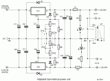 This is the voltage converter to get the voltage of ±1,25-30V from the input voltage of ±35V. I am using the 3 terminal voltage regulator for the voltage to be changed in this unit....
[read more]
 It is a simple circuit regulated power supply, based on the known LM 723, that drive a transistor Q1 [2N3055]. The regulation of voltage, of expense becomes with potentiometer R1 from 0v-30v DC roughly. In order to we achieve 30 V, will should the transformer of supply TR1, it gives all the current that it asks the load, differently the output voltage it will be found in the levels of 26 V roughly. Essential is the use of a good heatsink for transistor Q1, as well as good quality of potentiometer in the place of R1....
[read more]
 Many times we needed a stabilized, together regulated power supply and high relatively output voltage. These specifications him it cover our circuit. It 's a circuit that can give in his exit + 40V until + 60V 3A, with simultaneous stabilization....
[read more]
 Here they exist two regulator circuits, that use the IC L200, as regulator of voltage and current, the company SGS-Thomson, which give these circuits. In circuit Fig.1, we can regulate the output voltage, with the RV1, while in the Fig.2, we can regulate also output voltage current, with the TR2 and TR1, respectively. More information on characteristics for L200, you can see in list datasheets. Shortly will be added also certain other useful circuits with L200....
[read more]
 This circuit allows you to set a limit on the maximum output current available from your PSU. It's very useful when you power-up a project for the first time - or carry out a soak-test. By setting an upper limit on the current available from your PSU - you can protect both your power supply - and any device connected to it. It offers a simple and cheap alternative to the Current Limiting Power Supply...
[read more]
 This is a 1-amp variable-voltage PSU. It adjusts from about 3v to 24v: and has the added feature that you can limit the maximum output current. This is invaluable when (for example) you power-up a project for the first time or soak-test a piece of equipment....
[read more]
 This Power Supply is suitable for the Modular Burglar Alarm. However, it has other applications. It is designed to provide an output of 12-volts, with a current of up to 1-amp. In the event of mains failure, the back-up battery takes over automatically. When the mains is restored, the battery recharges....
[read more]
 This simple unit provides a dual-rail variable output ranging from ±2.5V to ±15Vdc with precise tracking of the positive and negative output voltages, still retaining the current limiting and short-proof capabilities of the "master" circuit. As the purpose of such a dual-rail design is to supply experimental or under-repair circuits, the maximum current output delivered was deliberately kept to about 500 - 600mA per rail, thus avoiding the use of expensive power transistors and complex circuitry....
[read more]
 Here is the simple virtual ground circuit based on discrete components. This simple design comes from miniaturization guru Sijosae. Is to make a buffer from generic discrete components. The transistors can be most any complementary pair of small-signal transistors. Suitable alternatives are the PN2222A and PN2907A. The diodes are generic small-signal types. An acceptable alternative is the 1N914. This circuit has better performance than a simple resistive divider virtual ground, and the parts cost is lower than for any other circuit mentioned here. It is, however, the least accurate of the buffered virtual ground circuits....
[read more]
 This circuit is a small +5V power supply, which is useful when experimenting with digital electronics. Small inexpensive wall tranformers with variable output voltage are available from any electronics shop and supermarket. Those transformers are easily available, but usually their voltage regulation is very poor, which makes then not very usable for digital circuit experimenter unless a better regulation can be achieved in some way....
[read more]