- Stablised Power Supply With Short-Circuit Indication
- 3-30V 3A Adjustable Regulated DC Power Supply
- 9 Volt 2 Ampere DC Power Supply Circuit Diagram
- Adjustable 1.3-22V Regulated Power Supply
- Adjustable Current Limit For Dual Power Supply
- Quad Power Supply For Hybrid Amplifier
- Stabilized Regulated Power Supply Circuit
- Transformerless 5 Volt Power Supply
- Variable Dc Power Supply
- High-Voltage Regulator With Short Circuit Protection
- Ampere or Current Booster Circuit
- Smoke Alarm Battery Life Extender
- High Current Regulated Supply
- 2 Watt Switching Power Supply
- Variable Voltage and Current Power Supply
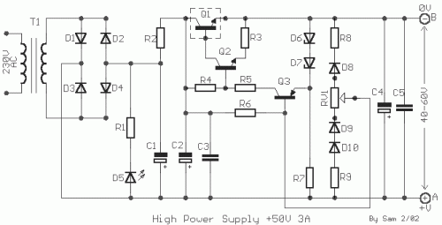
Power Supply +50V 3A stabilized and regulated
Discription
Many times we needed a stabilized, together regulated power supply and high relatively output voltage. These specifications him it cover our circuit. It 's a circuit that can give in his exit + 40V until + 60V 3A, with simultaneous stabilization. The materials that use is very simple and will not exist difficulties in the manufacture, is enough you are careful certain points. 1 ] For output voltages smaller of + 50V until + 40V, the Q1 is hot enough, so that it needs one big heatsink. 2]For output voltages bigger of + 50V up to + 70V, the stabilization is not satisfactory. Conclusion: ideal output voltage is + 45V until + 60V. In the circuit pontesometer RV1, is used in order to we change the output voltage between + 40V until + 70V, we can however and perhaps it should, him we replace with two constant resistors, when finishe the regulation, in the desirable price. The reason is, that with time is presented change of output voltage, up to 3V, with connected pontesometer. ATTENTION!!! The positive exit correspond in point [ A ] and the exit of 0V in point [ B ], which should not be connected in the ground.
Circuit diagram
Part list
- R1=10Kohm
- R2=1 ohm 5W
- R3=3.9 ohms 1W
- R4=6.8Kohm 1W
- R5=390 ohms 1W
- R6=100Kohm 0.5W
- R7=1.2Kohm 1W
- R8=1.8Kohm 0.5W
- R9=3.3Kohm 0.5W
- RV1=470 ohms pot.
- C1-2-4=4700uF 100V
- C3-5=100nF 250V MKT
- Q1=2N3055 on heatsink
- Q2=BD162 or BD243 or BD543
- Q3=BC303 or BC461
- D1....4=Bridge 15A
- D5=LED RED 5mm
- D6-7=10V 1W Zener
- D8-9-10=1N4007
- T1=230Vac / 55V 3A
