Low Voltage Step-Down Converter
Description
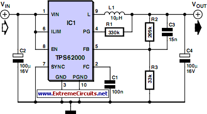
Sometimes you have a situation where you have a 5-V supply voltage but part of the circuit needs a lower supply voltage. A voltage regulator from the Texas Instruments TPS62000 family [1] is a good choice for this if the current consumption is less than 600 mA.
The essential advantages are:
- small (but still manually solderable) SMD package;
- high operating frequency (750 kHz) => small external inductor;
- integrated power MOSFETs => high efficiency (up to 95 %);
- no external switching diode necessary.
Circuit diagram:
You can thus use this device to build a very compact, highly efficient voltage converter. A sample layout generated by the author is available as a file on the Elektor website. The TSOP62000 provides an internal reference potential of 0.45 V, which can be used to set the output voltage in the range of 0.5 V to 5 V by means of resistors R2 and R3. The formula for this is: Vout = 0.45 V + (0.45 V) × (R2 / R3) For relatively low voltages, the value of inductor L1 should be 10 µH, but a value of 22 µH is better if the output voltage is 3.3 V or more. The input voltage can be anywhere in the range of 2 V to 5.5 V, and of course it has to be higher than the desired output voltage. The output voltage is 3.3 V with the indicated component values and an input voltage of 5 V. If you want to reduce the component count even further, you can use a member of the family with a fixed output voltage. The available voltages are 0.9, 1.0, 1.2, 1.5, 1.8, 1.9, 2.5, and 3.3 V. With this approach you can omit R2, R3 and C3, so the output can be connected directly to pin 5.
circuit from http://www.extremecircuits.net/2010/05/low-voltage-step-down-converter.html
