Simple Short-Wave Transmitter
Description
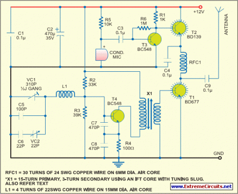
This low-cost short-wave transmitter is tunable from 10 to 15 MHz with the help of ½J gang condenser VC1, which determines the carrier frequency of the transmitter in conjunction with inductor L1. The frequency trimming can be done with VC2. The carrier is amplified by transistor T4 and coupled to RF amplifier transistor T1 (BD677) through transformer X1*. The transmitter does not use any modulator transformer.
The audio output from condenser MIC is preamplified by transistor T3 (BC548). The audio output from T3 is further amplified by transistor T2 (BD139), which modulates the RF amplifier built around transistor T1 by varying the current through it in accordance with the audio signal’s amplitude. RFC1 is used to block the carrier RF signal from transistor T2 and the power supply. The modulated RF is coupled to the antenna via capacitor C9.
Circuit diagram:
For antenna, one can use a 0.5m long telescopic aerial. Details of RF choke, inductor L1 and coupling RFC1 is used to block the carrier RF signal from transistor T2 and the power supply. The modulated RF is coupled to the antenna via capacitor C9. For antenna, one can use a 0.5m long telescopic aerial. Details of RF choke, inductor L1 and coupling transformer X1, we used a ready made short-wave antenna coil with tuning slug (Jawahar make), which worked satisfactorily. We tested the transmitter reception up to 75 metres and found good signal strength.
circuit from http://www.extremecircuits.net/2010/05/simple-short-wave-transmitter.html
