- Long Delay Timer Circuit Diagram
- Jogging Timer Circuit Diagram
- Amplifier Timer Circuit Schematic
- A Very Useful Timed Beeper Circuit Schematic
- A Bedside Lamp Timer Circuit Schematic
- Safety Guard
- Midnight Security Light Circuit Schematic
- Power-Off Time Delay Relay
- Power-On Time Delay Relay
- Generating a Delayed Pulse Using The 555 Timer
- 555 timer Mono stable (one shot) circuit
- Generating Long Time Delays
- Low Voltage, High Current Time Delay Circuit
- 9 Second Digital Readout Countdown Timer
- 9 Second LED Timer and Relay Circuit
Repeating Timer No6
Description
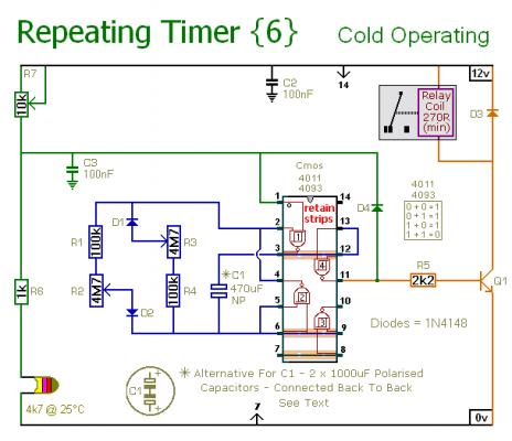
This timer circuit will only run when the temperature falls below a preset level. There's an alternative version - Repeating Timer No.5 - that only works while the temperature is above the preset level.
R7 lets you set the temperature. The value of the thermistor is not critical. The important thing is the voltage on pin 1. Any value thermistor should work satisfactorily. But you may need to change the value of R7 - to achieve the desired range of adjustment.
Schematic Diagram
Setting The Timer
The circuit is basically an Astable Oscillator. And the output times depend on the value of C1 - and the speed at which it charges and discharges through the resistor network. The length of time the relay remains energized is controlled by R1 & R2. And the length of the time it remains de-energized is controlled by R3 & R4. The fixed resistors set the minimum period lengths - and the maximum period lengths are set by R2 & R3. With the component values shown - both periods are adjustable from about 1 to 30 minutes.
You can change the component values to suit your own requirements. If your time periods don't need to be too precise - and more-or-less is close enough - you can leave out the pots altogether - and simply rely on R1 & R4 to set the times. Owing to manufacturing tolerances - the precise length of the time periods available depends on the characteristics of the actual components you've used - and a 4093 will produce longer time periods than a 4011.
IMPORTANT
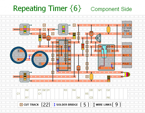
Do not use the "on-board" relay to switch mains voltage. The board's layout does not offer sufficient isolation between the relay contacts and the low-voltage components. If you want to switch mains voltage - mount a suitably rated relay somewhere safe - Away From The Board. I've used a SPCO/SPDT relay - but you can use a multi-pole relay if it suits your application.
Alternative Capacitor
When the oscillator is running - the polarity of the charge on C1 keeps reversing. So C1 needs to be non-polarised. However - you can simulate a non-polarised 470uF capacitor by connecting two 1000uF polarised capacitors back to back - as shown. How and why this works is explained in the Detailed Circuit Description. Because non-polarised capacitors aren't widely available - the prototype was built using two polarised capacitors.
Veroboard Layout
Setting The Temperature
When R7 is turned all the way to the left - it connects pin 1 to the positive line. So the timer will run - regardless of the temperature of the sensor. In other words - there is no upper limit on the temperature setting. And - when R7 is turned all the way to the right - the operating temperature is below 0ºC (32ºF).
This wide range makes the adjustment coarse. You can improve control by connecting a new fixed resistor (R8) in series with R7 - and reducing the value of the pot to say 1k. R8 will replace the link from pin 14 to the R7 pole. (It's the link immediately to the right of the IC). Choose a value for R8 that will take you close to the desired temperature - and use the reduced value pot to make the fine adjustment.
Setting the operating temperature is best carried out "in situ" - using trial-and-error. If the timer starts at too high a temperature - turn R7 a little to the right. If it starts at too low a temperature - turn R7 a little to the left.
The following readings will give you some idea of what to expect. They are taken from the prototype. They apply to the Cmos 4011. And they were made using a cheap digital multimeter and a cheap thermometer. They are intended for guidance only. You should NOT expect to get identical readings.
My thermistor measured 4.45K at 25ºC (77ºF). My supply voltage measured 12v4. And the Pin 1 switching point was measured at 7v3. With R7 set to 8k - the timer worked at temperatures below about 5ºC (41ºF).
Temperature Sensor
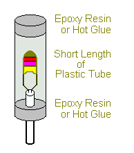
The mass of the thermistor is small - and it will react quickly to changes in temperature. This makes it sensitive to thermal currents. One solution is to create an enclosed environment - where the thermistor is protected from momentary draughts - but can still respond to slower changes in the overall ambient temperature.
The Supply Voltage
The timer is designed for a 12-volt power supply. However - it will work at anything from 5 to 15-volts. All you need do is select a relay with a coil voltage that suits your supply. I used a single pole relay in the prototype - but you can use a multi-pole relay if it suits your application.


