A Very Simple LED Tester
Circuit diagram:
Description
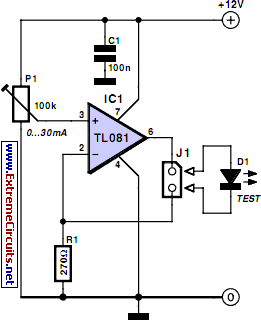
This simple LED tester consists of a current source with a potentiometer that can be used to adjust the current. The current source is implemented using a type TL081 opamp. The output current of the opamp flows through the diode and R2. The voltage drop across R2 is fed back to the inverting input and compared with the reference voltage, which is set with R1 and applied to the non-inverting input.
The adjustment range is approximately 0–30 mA, which is suitable for testing all normal LEDs. If you wish, you can connect a multimeter across the LED to measure the voltage on the LED. For the power source, a good option is to use a small laboratory power supply with the output voltage set to 5 V. It is convenient to fit the potentiometer with a scale so you can see directly how much current is fowing through the LED. In order to calibrate the scale, you can temporarily connect an ammeter in place of the LED.
