similar circuits
- Controlling a relay with a digital logic level.
- Monostable Flip Flop
- Bistable Flip Flop
- Set/Reset Flip Flop
- LED Traffic Lights
- Frequency Divider with 7490
- Frequency Doubler with 4011
- Frequency doubler with 4069
- Frequency Divider
- Digital Clock with MM5314N
- Digital Step-Km Counter Circuit Schematic
- 7 Segment LED Counter
- Digital Step-Km Counter
Frequency Divider
Description
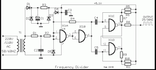
This is a classic divider of frequency via two. It is achieved with a classic circuit T-flipFlop, round IC1 [ 4011 ]. In the circuit, the frequency of network, after are limit the negative half-s period of sine wave and transform in square wave, are divided via two. Thus for frequency50 HZ, we will take in the exit pulse of frequency 25 HZ. The supply of circuit it is + 5V and does not need high benefit in current.
Circuit diagram
Part list
- R1= 10Kohm
- R2= 100Kohm
- R3= 680 ohm
- R4= 1Mohm
- R5-6-7= 100Kohm
- R8= 47 ohm
- R9-10-11= 100Kohm
- C1= 1000uF 25V
- C2-3= 100nF 100V ceramic
- C4-5= 100pF ceramic
- IC1= 4011
- T1= 110/220Vac //8V 100mA
- D1-2= 1N4007
- D3= 5.1V 0.5W Zener
- D4-5= 1N4148
circuit from http://users.otenet.gr/~athsam/frequency_divider.htm
