Electronic Dice
Description
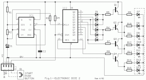
The IC1 is a 555 timer IC is connected for, Astable operation the clock pulses are fed to the IC2 via the 10K resistor. The IC2 is a 10 stage counter, output 6 (pin 5) is connected to RESET (pin 15), thus giving us a 6 stage counter , outputs 0 to 5. The 6 of the LEDs are connected as 3 pairs, thus requiring 4 different signals, these signals come from the 4 transistors, which in turn are connected to the necessary outputs of the IC2. Where a transistor is operated from more than one output, diodes are used to avoid a short circuit situation between outputs. Pin 13 of the IC2 (INHIBIT) is connected to +ve via a 100K resistor to stop the counter from advancing, however pressing the S1 [START] button will connect pin 13 to 0V line and allow the counter to advance, hence, throwing the dice. The circuit supply can use a 9V battery or external pack 9 until 12V. The D7 until D15 LEDs connected as Fig.2 to make a dice.
Circuit diagrams
Part list
- R1-2=2.2Kohms
- R3=10Kohms
- R4=100Kohms
- R5.....8=8.2Kohms
- R9.....5=1Kohms
- C1=22uF 25V
- C2=10nF 100V MKT
- D1.......6=1N4148
- D7.......13=Red Led 5mm
- IC1=NE555 or LM555
- IC2=4017B
- Q1....4=BC550
- S1=Normal Open Push switch
- SL1=4pin connector 2.54mm step
- BATT=9V battery or 12V ext.
circuit from http://users.otenet.gr/~athsam/electronic_dice_2.htm

